![0227211105_HDR[1].jpg](https://cdn.head-fi.org/a/11441897.jpg)


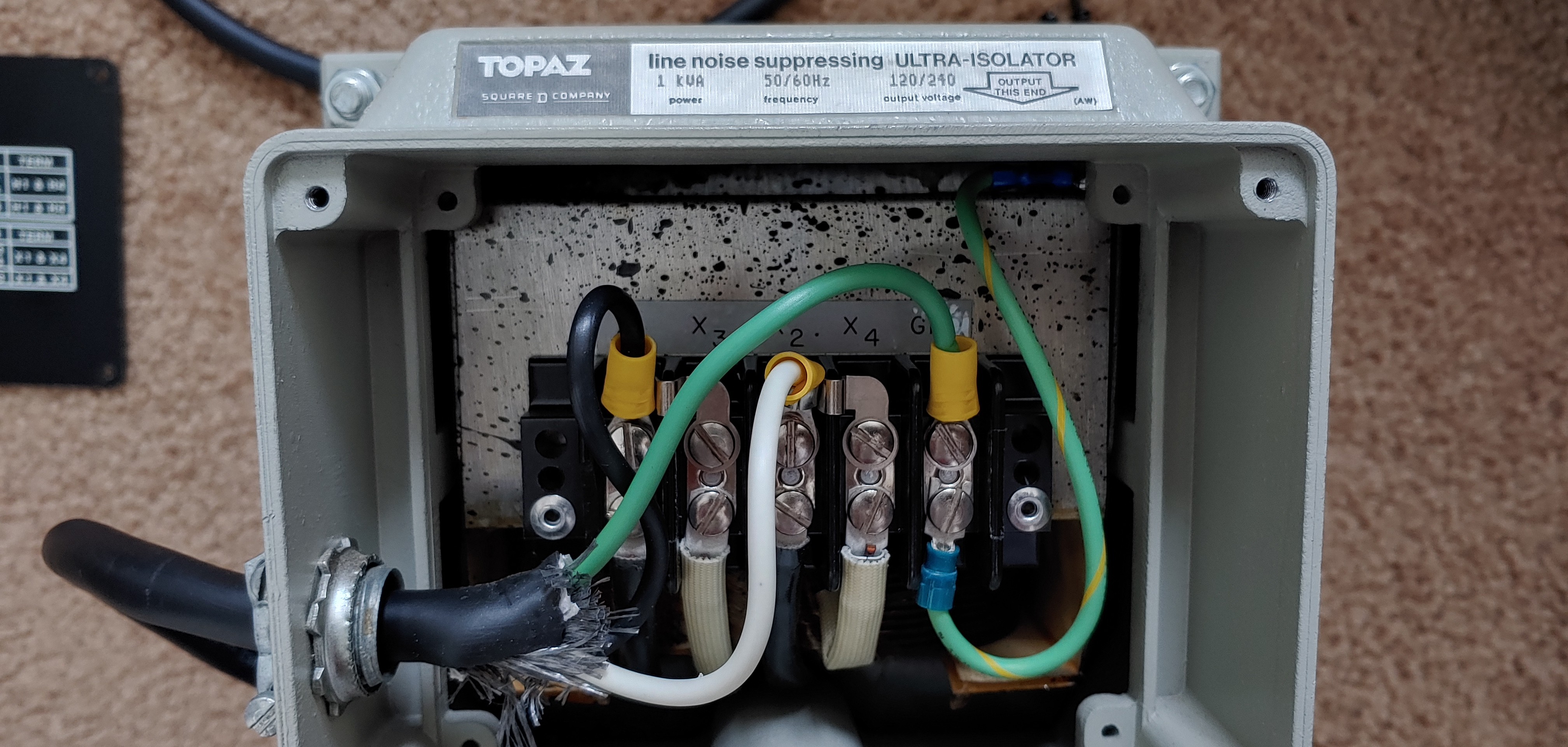


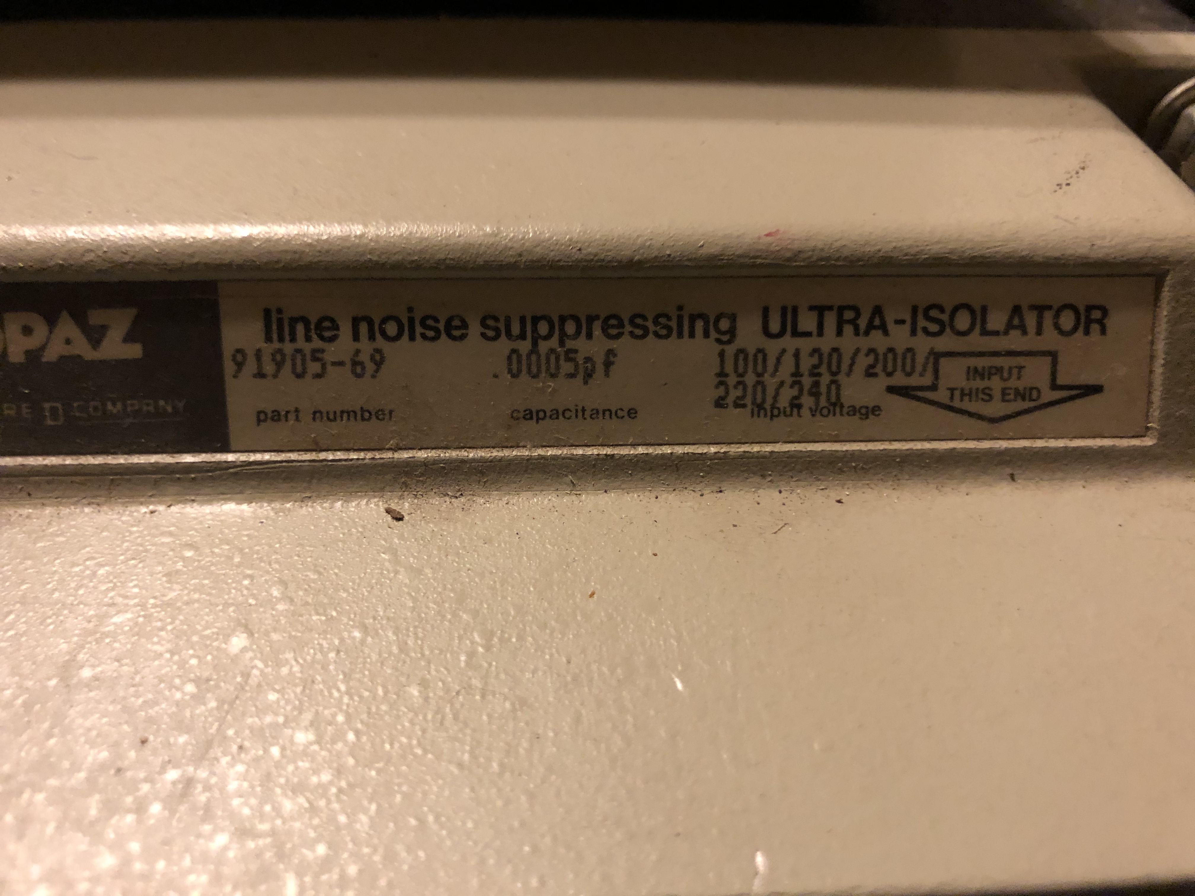

I have a topaz 91097-31. Does anyone know if it uses a replacable fuse and if so what size and spec? I want to try a better fuse...
Last edited:
Thanks. I believe this is correct based on confirmation from others...https://www.surplussales.com/Transformers/Pdfs/tp-91092-31_N.pdf
In this manual, which covers your 91097-31 as well, there is no mention of a fuse - replaceable or not.
https://www.ebay.com/itm/1738078112...llYj8wxQKG&var=&widget_ver=artemis&media=COPYI followed this thread from the beginning and I could never find a big topaz with reasonable shipping to where I live in hawaii.
Hello oneguy. I've read through this entire thread and I still have a few questions one some things for wiring for balanced. I have a terminal equipped 2.5kva 0.0005pf MGE. I've wired it as you mention so far but here's a few questions: Are you supposed to run a wire jumper on the ground on the *input* side over to the jumpered H3 & H2? Is the input equipment grounding conductor going to the power cord supposed to actually be wired to the input ground or to the jumpered H3 & H2? The thing that makes me wonder about this, is that on the input side, unlike the output, there are actually 2 ground wires, there's a chassis ground, and there's also another ground that runs internally to the transformer itself, whereas on the output side, there is only a chassis ground. Correct me if I'm wrong, but it seems to me that if there's a ground running directly to the transformer that should be grounded through the power cord to the wall, or does it matter? I had already wired this up and tested it with no chassis grounding on either the input or output (no ground wire jumped over to the jumpered X3 & X2 center tap). I got the correct measurements on a multimeter and even powered up a monitor with it. I have both grounds running off of the jumpered center taps on both input and output--if this is definitely wrong, like for the input, let me know.Balanced wiring happens on just the output side but the input side will need to be changed from the 120v wiring setting. You wire the input side for 240v (jumper H2 and H3) and wire the output side for 240v (jumper X2 and X3). The balance wiring comes in when you wire X2 or X3 (it doesn’t matter which one) to ground.
Balanced wiring diagram:
-The 240v setting on the output side allows you to have a center tap (X2 or X3) to ground which you need for balanced power.
-The 240v setting on the input side side allows the input side to be 1:1 with the output side (both sets of input coils and output coils are now in series in the respective sides). If you left the input set up for 120v this would cause a step up in voltage.
-Grounding the center tap allows the wave forms to be halved thus creating two 60v sine waves 180 out of phase with each other.
No, no terminal from H1 through H4 should be grounded.Are you supposed to run a wire jumper on the ground on the *input* side over to the jumpered H3 & H2?
Input ground.Is the input equipment grounding conductor going to the power cord supposed to actually be wired to the input ground or to the jumpered H3 & H2?
You are correct. The transformer should be grounded through the wall.Correct me if I'm wrong, but it seems to me that if there's a ground running directly to the transformer that should be grounded through the power cord to the wall, or does it matter?
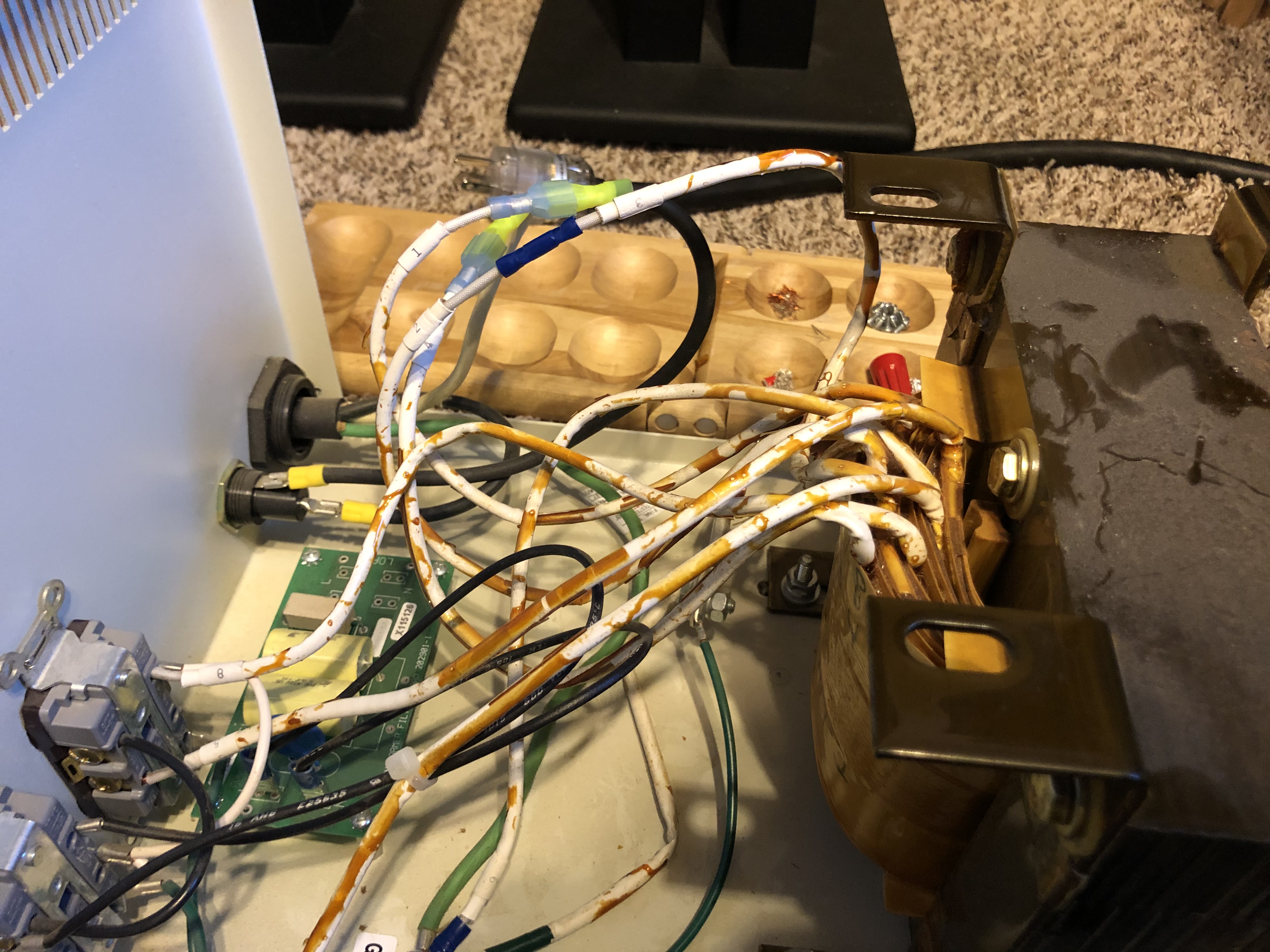
None of the taps on the input side should be grounded. On the output side, only the X2 or X3 should be grounded. I have attached pic below to illustrate the wiring.I got the correct measurements on a multimeter and even powered up a monitor with it. I have both grounds running off of the jumpered center taps on both input and output--if this is definitely wrong, like for the input, let me know.

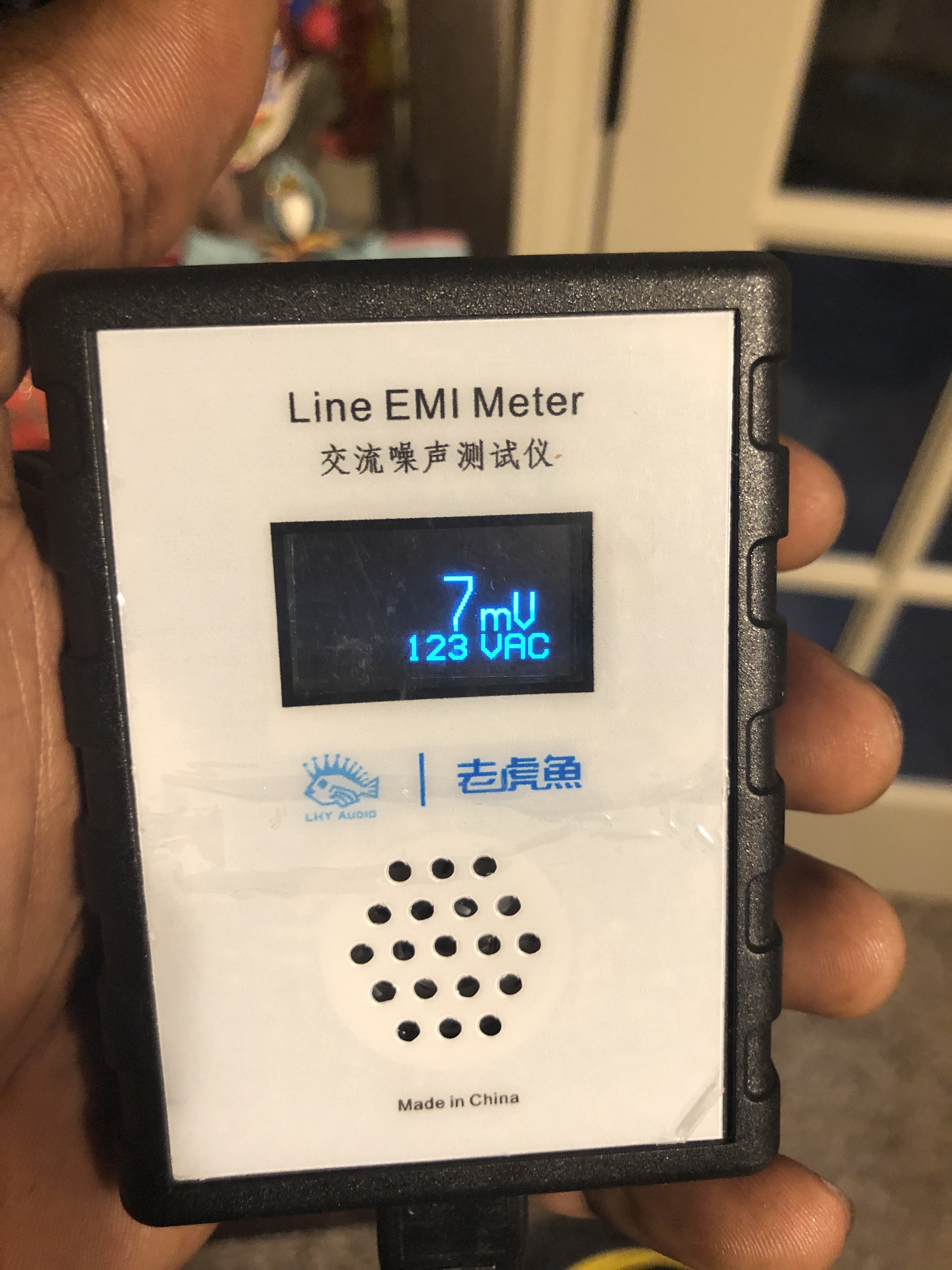
Thanks, I got it wired correctly, performed all measurements, Made sure H1 and H4 resistance measurement to the case ground read as an open circuit as you had emphasized in a previous post. Installed and running perfectly. Having previously had H3&H2 connected to the EGC was probably what was causing the AFCI breaker to cut all power, lol, because it does not do that now. Like I said though I did have it temporarily powered up for about an hour with the input center tap grounded & plugged in another iso tranny so it wouldn't trip the AFCI, and I didn't notice any ill effects and it still measured 60v on the output from both hots to center tap. Hopefully I didn't damage anything with it like this? But it appears to be all good now wired correctly. I actually already implemented exactly what you said before I read your post, (based on deductive reasoning and further analyzing things) and thank you for taking the time to respond, confirming the correct wiring. The thing is pretty incredible at noise reduction. I have a line emi meter, and one circuit on a different iso xformer where my extremely noisy PC is plugged into it (the secondary of that xformer is blocking 99.99% of that noise from backfeeding into the mains) - but on it's secondary, there's 1500+ mv (1.5+ V) of noise circulating around there and the 0.0005pf MGE drops that down to around 80-90 mv with no output filter cap even (and this was before I had the grounding wired correctly--so it may even be better now).None of the taps on the input side should be grounded. On the output side, only the X2 or X3 should be grounded. I have attached pic below to illustrate the wiring.
White is neutral, black is hot, the short black lines from H2 to H3 and X2 to X3 are jumpers, Green is ground. Does that clear it up?
Nope, the transformer will be fine. This wouldn’t have created any damage to it.Hopefully I didn't damage anything with it like this?
Yep, correct. H1/X1 can be black and H4/X4 can be white or the opposite (H1/X1 can be white and H4/X4 can be black). It doesn’t matter.Edit: I have the H1 and X1 as black and H4 and X4 as white, but does it even matter either way, as long as both are the same from primary through secondary? A previous post you stated:
"Black to H1, white to H4. Black to X1, white to X4"
